
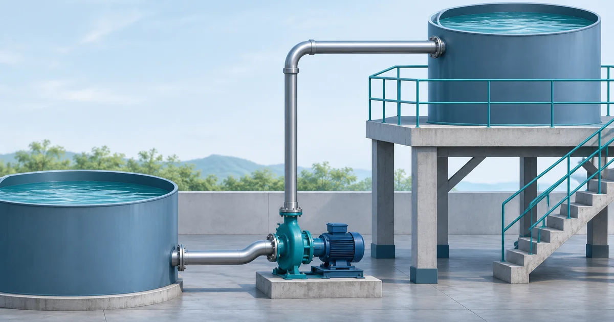
To choose a pump, you need to know how much liquid it must move and how hard it must work to move it. Pump head describes that work. This guide shows how to make a first estimate for a simple system and which details to give a supplier.
For water moving between two large tanks open to the air, start with the difference in water levels. Then add the estimated losses caused by the pipes, fittings and equipment at your chosen flow. The result is called total dynamic head, or TDH.
More complex systems may also require pressure and velocity-head terms. The result is a requirement at a stated flow, not the same thing as the highest point of the pipe or a pump's maximum catalogue head.
A quick example
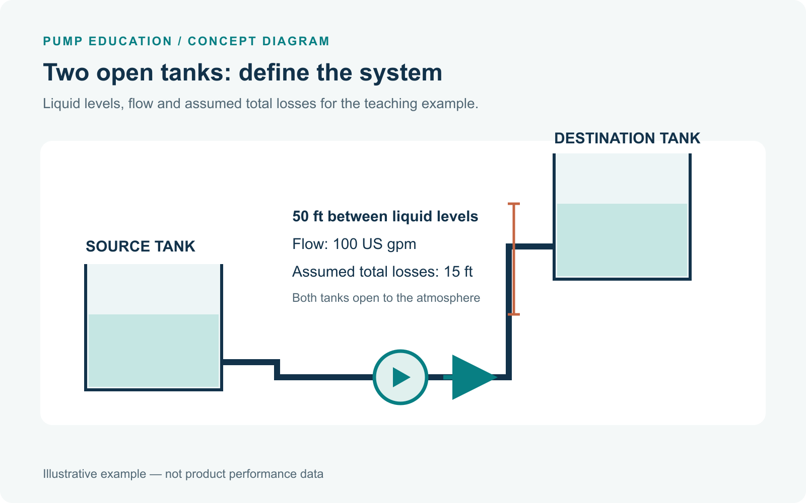
Two open tanks; losses are assumed for teaching.
Say the water level in the destination tank is 50 ft higher than in the source tank. At a flow of 100 US gallons per minute (gpm), assume the pipework and equipment add 15 ft of loss. The estimated requirement is 50 + 15 = 65 ft of head at 100 gpm.
These numbers are for teaching only. The 15 ft loss is assumed here; a real project needs losses calculated from the actual pipework and equipment. Both tanks in this example are open to the air. Other systems can need pressure and velocity terms too.
What is pump head?
Pump head describes the energy added to the liquid per unit weight, commonly expressed in feet or metres of the pumped liquid. For selection, the system's required head at the design flow is compared with the pump's performance curve.
Pressure and head are related but are not interchangeable without considering fluid density. For water-like liquid with a specific gravity near 1, 1 psi corresponds to approximately 2.31 ft of liquid head. For another liquid, the same pressure difference corresponds to a different head:
Pressure head (ft) ≈ pressure difference (psi) × 2.31 / specific gravity
Use the actual liquid properties and a consistent pressure basis. The Hydraulic Institute describes pump total head as the difference between total discharge and suction head.
Information to collect before calculating
| Input | What to identify |
|---|---|
| Liquid and temperature | Fluid, temperature, density, viscosity and any relevant solids |
| Required flow | Normal flow and expected operating range; specify units |
| Reference points | Inlet and outlet locations chosen for the system energy balance |
| Liquid levels | Expected source and destination levels at operating conditions |
| Pressure | Pressure at each reference point, using the same gauge or absolute basis |
| Piping | Actual inside diameters, lengths, material and condition |
| Components | Bends, valves, strainers, filters and equipment pressure losses |
| Operating conditions | Pump speed, number of pumps, level variation and other changes that affect the system |
If the system has not yet been designed, estimates should be labelled and updated when actual pipework, equipment and operating conditions are known.
How to calculate pump head step by step
1. Select the two reference points
Choose the points between which the liquid's energy change and system losses will be evaluated. For two tanks, the liquid free surfaces are often convenient. Record each elevation and pressure relative to a consistent reference.
2. Calculate the static elevation difference
Subtract the source elevation from the destination elevation: z₂ − z₁. Use the actual operating liquid levels. If the source surface is below the pump and the destination surface is above it, the level difference includes both portions; avoid counting either twice.
In a closed circulation loop, the net elevation difference around the same reference level may cancel, but pipe and equipment losses still need to be overcome. The actual arrangement must be checked.
3. Account for pressure and velocity differences
If one reference point is pressurized, calculate the difference between destination and source pressures and convert it to head using the liquid's density. Use pressures on the same basis. Include a velocity-head difference when the selected reference points make it significant; free-surface velocity in sufficiently large tanks is often approximated as zero.
4. Calculate losses at the design flow
Include friction in suction and discharge pipework, losses in fittings and valves, and applicable filter or equipment losses between the chosen reference points. Pipe internal diameter, material, condition, fluid properties and flow matter. Use an appropriate engineering method and equipment data; do not treat an assumed loss as a measured value.
5. Add the terms and check the duty point
Add elevation, pressure and velocity differences and total losses in consistent units. Pair the resulting head with the flow used to calculate losses. Repeat the system calculation as needed across the expected flow range to establish a system curve, then compare it with the correct pump curve.
Worked example: water transfer between two open tanks
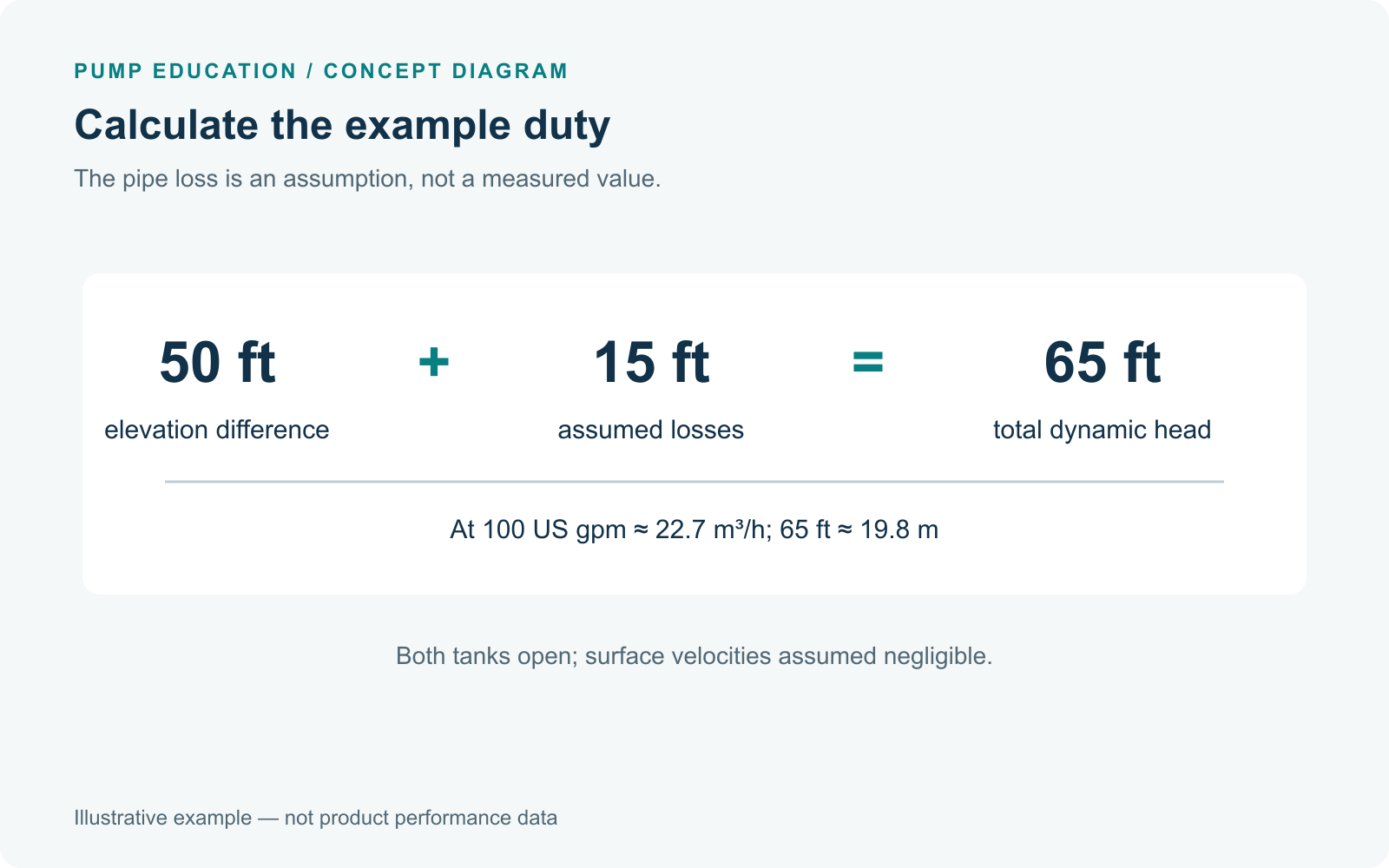
Illustrative calculation; the pipe loss is assumed, not measured.
This is a fictional teaching example. It is not a measured installation or a specification for any product.
Assume water-like liquid, both tank free surfaces open to the same atmosphere, and negligible surface velocity. The destination surface is 50 ft above the source surface. At a design flow of 100 US gpm, the assumed total suction and discharge pipe, fitting and equipment losses combined are 15 ft. The example does not derive those losses from pipe dimensions; they would need a real calculation for an actual project.
| Component at 100 US gpm | Assumed value |
|---|---|
| Free-surface elevation difference | 50 ft |
| Pressure-head difference | 0 ft; both surfaces open to the same atmosphere |
| Velocity-head difference | Approximately 0 ft at the selected free surfaces |
| Total losses, already including fittings and equipment | 15 ft |
| Estimated total dynamic head | 65 ft |
TDH = 50 + 0 + 0 + 15 = 65 ft
Thus, the estimated design requirement is 100 US gpm at 65 ft TDH. If your pipe losses are unknown, do not guess that they are 15 ft: gather the pipe lengths, inside diameters, fittings and equipment data, and ask a qualified person to calculate them. In metric units, that is approximately 22.7 m³/h at 19.8 m. This is the same assumed system duty used in our pump-curve reading example. It does not prove that a particular pump meets the duty.
For a deeper check: the full head equation
For a steady, single-liquid system between chosen reference points 1 and 2, a common energy-balance form is:
TDH = (z₂ − z₁) + (p₂ − p₁)/(ρg) + (v₂² − v₁²)/(2g) + hL
Here, z is elevation, p is pressure, ρ is liquid density, g is gravitational acceleration, v is velocity, and hL is the total head loss between the reference points at the specified flow. Every term must use compatible units. The equation assumes the stated system boundary and that relevant energy additions or removals have been accounted for.
For two large tanks open to the same atmosphere, with negligible velocity at both free surfaces, the pressure and velocity differences at those reference points are approximately zero. The calculation then simplifies to:
TDH ≈ difference in free-surface elevation + total piping and equipment losses
This simplification is not universal. A pressurized vessel, a discharge nozzle as the reference point, a significant velocity difference, a changing liquid level or another system arrangement changes the calculation. Do not add fitting or exit losses twice if they are already included in the stated total losses.
How to use the result on a pump curve
Provide the flow and corresponding total head to the supplier, together with liquid properties, source conditions and electrical supply. Compare the system curve with the correct pump curve for the offered impeller and speed. Review the operating range, efficiency and power as well as NPSH available and required. If you are considering a stainless steel centrifugal pump, request the performance curve for the exact offered model.
TDH and NPSH are related to the same system but answer different questions. TDH describes the required energy addition across the selected system boundary; NPSHa addresses suction conditions at the pump inlet. Do not simply add NPSH to TDH as a generic allowance. Our pump cavitation guide explains why suction conditions require a separate check.
Common calculation mistakes
- Using vertical lift alone while omitting friction, equipment losses or a pressure difference.
- Using nominal pipe size as the actual internal diameter without checking.
- Adding fitting losses twice after using a total loss that already includes them.
- Mixing feet and metres, or US gpm and another flow unit.
- Applying a water pressure-to-head conversion to a different liquid without accounting for specific gravity.
- Using a single assumed loss as if it were valid at every flow.
- Comparing a 50 Hz pump curve to an offered 60 Hz configuration without confirmation.
Frequently asked questions
Does pump head mean the vertical height of the building?
Not necessarily. Elevation can be one component, but pressure differences and system losses also matter. In a closed loop, the relevant elevation terms depend on the selected boundary and may cancel.
Does a pump with a 65 ft maximum head meet a 100 gpm at 65 ft duty?
Not necessarily. The maximum head may occur at a different flow, including shutoff. Check the offered model's head-flow curve at 100 gpm and the applicable operating limits.
How much safety margin should I add?
There is no universal percentage appropriate to every installation. Excessive allowances can move a pump away from its intended operating range. Have the system designer review uncertainties and the supplier's equipment-specific requirements.
Further reading: U.S. Department of Energy, Improving Pumping System Performance; Pump Systems Academy, Total Dynamic Head calculation.
PUMPSHUB · PROJECT INQUIRY
Have a flow and head requirement?
Send your expected flow, system head, fluid, voltage and quantity. We can discuss the available pump information for your project.